
Step Installation Instructions
Unboxing

Tools and hardware

Steps and rail clamps
Assembly
For your convenience, our team has fully pre-assembled the step portions so they are ready for installation out of the box.


Installation part 1
Checking the rail spacing for clamp fitment
Your OEM rock slider rail was designed to have approximately a quarter of an inch of adjustability. As such, spacing between the rail and the vehicle is extremely inconsistent from the factory. On some vehicles, there will be plenty of spacing to fit our clamps with no further adjustment. On other vehicles, some or none of the clamps will fit. If you have spacing issues, please follow part 2, otherwise you may proceed to part 3.
Installation part 2
Adding rail space for clamp fitment

The OEM rock slider rail attaches to the vehicle body with 13mm bolts as marked with the red arrow and through the pinch weld with 10mm nuts as marked by the blue arrows. 2-door JL Wranglers will have 2 of these connections, 4-door JL Wranglers will have 3 of these connections and JT Gladiators will have 4 of these connections.

Fully remove all 10mm pinch weld bolts as marked by the blue arrow, and loosen the 13mm bolts about 50-60 percent, but do not fully remove. When you pull the rail out from the vehicle, you want the 13mm bolt to stay in place in order to stop it in the maximum outward position.
Pull the rail out until it clicks into the fully outward position in all areas.
Installation part 3
Placing the clamps onto the rail
Parts needed

Upper clamp pieces made of carbon steel with a specialized 3-layer coating, marked left and right

Lower clamp pieces made of rust and impact resistant alloy, intended to stay on the rails for all but the most extreme off-roading, such as rock crawling

3mm T-handle and screws for attaching upper and lower clamp sections with extra screws if needed for later use

Optional: Adhesive rubber gaskets to put on the steel upper clamp portion where it meets the alloy lower portion for those who live in rust-prone areas; adhere prior to placing the clamps if you wish to use
Once there is adequate space between the rail and the vehicle, it is time to place the top clamp pieces. Whether you are installing 1 or 2 steps, place all upper clamp pieces on the rail.
If you had to loosen and adjust your rail, once all upper clamp pieces are placed onto the rail, it is now time to tighten the rail down.

Locate the metal spacers, which will go onto the pinch weld bolts as seen in blue. Place 2 per threaded section.

With the rail pulled all of the way out still, fully tighten down all 13mm bolts as seen in red first. Then, place 2 stainless spacer rings per pinch weld screw and tighten the 10mm nut. Repeat at every position until finished.
Installation part 4
Positioning the steps
The most important aspect of the Cross Terrain step installation process is properly aligning the clamps so that the step portion can properly align with the clamps for quick and easy removal and reassembly of the step. Our patented clamp system was designed and intended to stay on your factory rails for all but the most extreme off-roading conditions. For most uses besides rock crawling where the rails would be repeatedly sliding on or making hard contact with rocks, the clamps can stay on. Once the clamps are in position, adding and removing the steps is a quick and easy process.

Our patented clamp design is intended to allow the user to place steps wherever desired along the rock slider rails. Please note, there are some raised portions on parts of the rail that could interfere with proper alignment between the step and the clamp.

Should you wish to position a step near one of these raised portions, it is advised to move it a fraction of an inch left or right to avoid the step frame making contact and preventing proper alignment with the clamp.
Keeping in mind the raised parts of the rail as mentioned above, use the width of the step to estimate the spacing of the clamps. Align the left lower clamp portion with the left top portion and put the 3mm screws in. Only turn each screw a few times so the clamps can be mostly pulled apart for adjustment as needed.
Once you have finalized where you’d like the step to be, fully tighten the 3mm screws. While tightening, make sure the clamp stays straight on the rail. Avoid fully tightening one side at a time, as it is best to go back and forth to keep the clamp even and level until the process is complete.
Repeat the process on the right side, making sure to only turn each screw a few times; enough that the clamps will not fully come apart, but leaving enough separation to move left or right as needed to fine-tune the final placement.
After the left side is in a fixed position, it is time to finalize placement on the right side. With the right side clamp screws still mostly loose, squeeze the clamp together and gently place the step on the clamps to determine final spacing. Adjust the clamp left or right until the alignment is correct and all threads of the clamp align with the holes in the step frame. Gently remove the step to not move the clamp and tighten down fully like the left side once in place.
Encountering a misalignment
When installing the clamps, especially for the first time, you may encounter a misalignment between the frame holes and threads in the lower clamp. Here are a few common reasons why this may happen and how to rectify it.

Misalignment issue 1: As seen by the blue arrows, the clamp spacing is correct, and the fitment and alignment between the 2 clamps is good. Despite slightly adjusting the step slightly on the clamp, the hole and the threads will not fully align.

Solution: The step side-frame is likely contacting one of the drop-down pieces of the rail, preventing the step from seating all the way back on the clamp. Reposition the clamps slightly so that the step side frames do not contact these rail appendages. When the clamps are properly positioned and spaced, the threads should be easy to align.

Misalignment issue 2: The left side of the step and clamp are making contact, as seen by the yellow arrow. The right side is misaligned as seen by the red arrows and the gap between the step frame and clamp is too big, as shown by the blue arrows.

Solution: The clamp spacing is off and the clamp may not be sitting straight on the rail. Slightly move the clamp left or right to better align and make sure to keep the clamp straight when tightening. Tightening the clamp together a little bit one side at a time will help keep it straight.
Installation part 5
Connecting the steps to the clamps
Parts needed

You will need (8) M6 screws, a 4mm T-handle and 4mm bit, which we have provided. The 4mm bit is optional if wish to use it with your own tool, however, we highly recommend using the included T-handle for the final tightening.
M6 rubber gaskets, which are intended to help prevent the screws holding the step onto the clamp from damaging the finish, which could produce light surface rust.
Once the clamps are in place with correct spacing, adding and removing the step portion is a quick and easy process. Aligning the grooves on the clamps with the indents on the step frames, slide the step frame on into position.

Place one of the included rubber gaskets into each screw hole to protect the finish and prevent surface rust. The adhesive side should go against the screw head. We have provided extra for use as needed.
To secure the steps to the clamps, start by putting all screws in part way to allow some give. This will allow for some final adjustment when fully tightening.
Finish by moving the step into the desired position, centering the screws as best as possible and securing the screws. Use the top T-handle to tighten all the way, as you are least likely to damage the screws with this angle. Be very careful not to over tighten. Over tightening can possibly deform the screws or cut into the finish, which will allow mild surface rust to form. If any extra rubber is sticking out, you can peel it away. Repeat the process for all steps.
Functionality Notes

M6 Bolts: The M6 bolts provided with your Cross Terrain steps have gone through a special hardening process. They are custom made for this specific application and the tensile strength of these bolts are several times stronger than the typical off-the-shelf bolts at a hardware store. They are a high-tensile grade 12.9, the highest possible available. Additionally, they are not the primary weight-bearing connection between the step and clamp. Our thread design also features a locking design that will prevent the bolts from loosing during normal use. The bolts just need to be tightened down well upon install and no thread locker is needed.
Mechanical Tongue and Groove: The step side-frame and lower clamp have a tongue and groove just below the m6 bolt. This design is responsible for a significant part of the step weight distribution, not the M6 bolt alone. The M6 bolts and mechanical tongue and groove can each sustain the steps weight rating on their own, with room to spare. Under normal circumstances, each portion (the M6 bolt and tongue and groove) are only getting a small fraction of their weight ratings with little stress on either component. In case of any failure, each attachment component can sustain the weight rating on its own, indefinitely.

Step Flex and Movement: The factory rock slider rail our Cross Terrain Steps attach to is designed from the factory to have some flex. When developed by Jeep, the intended use is to take light to moderate impact, and as such, some give is needed. Our steps when properly installed should not have notable play or flex on the rail; however, the full rail should have some flex by design. This is no different than most running boards and is both normal and expected.
Is Your Rail Well Tightened?: Whether you needed to pull your factory rail out or not. It is a good idea to make sure the nuts and bolts on the factory rail are well tightened down if you are noticing a significant amount of movement. Often times, more flex than normal is directly related to a loose rail. This is especially true for loose pinch-weld nuts.
Maintenance and rust prevention
Cross Terrain steps are made using a premium multi-coat process. Prior to powder coating, an electrophoretic zinc coating is applied for durable, corrosion resistance. As long as this coating stays in tact, corrosion is very unlikely. Should parts of the coating be damaged to the bare steel, it is recommended to touch it up to prevent rust and preserve the appearance of your steps.
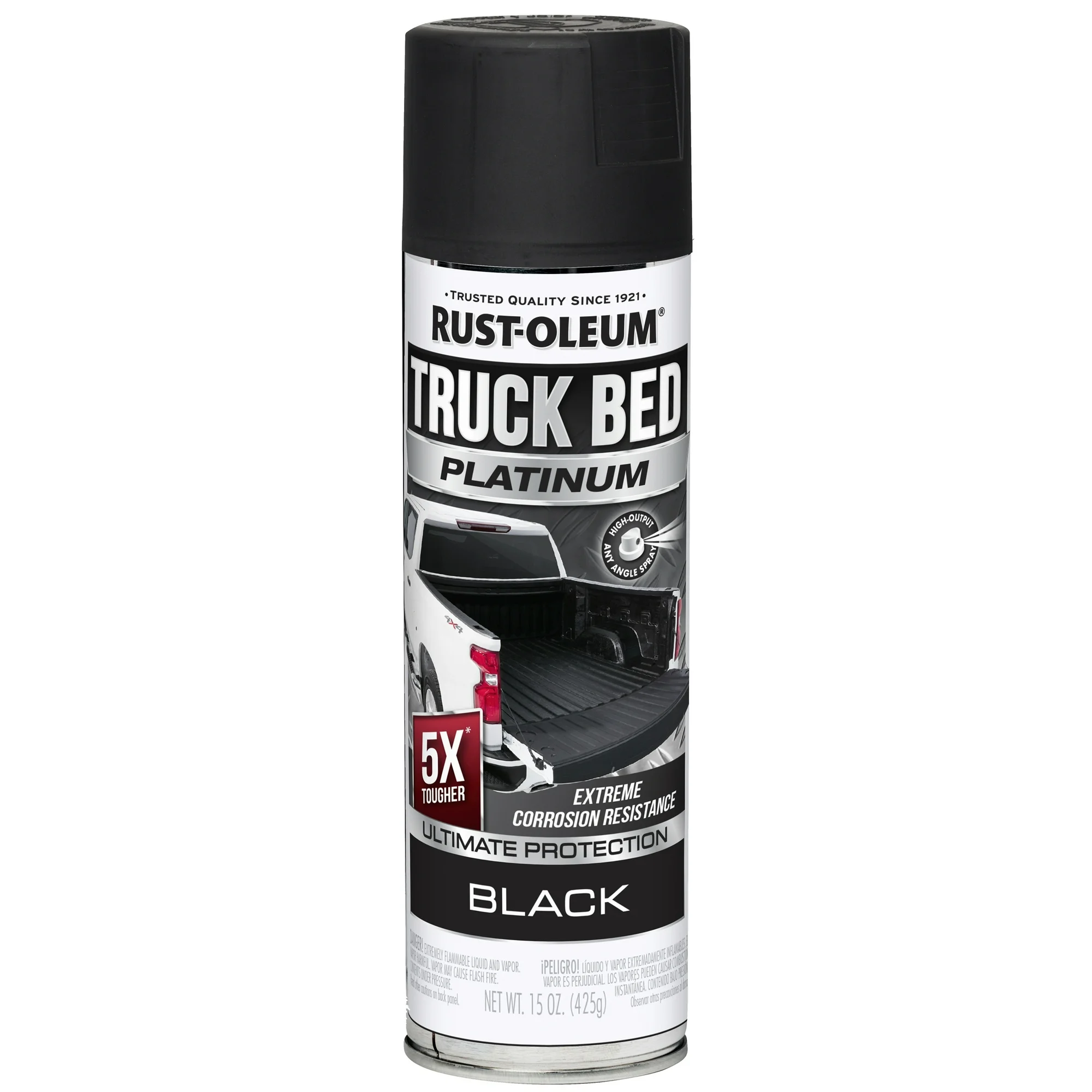
We have found Rust-Oleum platinum truck bed coating matches the factory rock slider rails and our original powder coating well and is easy to find. The textured aspect is much less than other bed liners and preserves the OEM rail-like texture we create with the original coating. This is a great way to quickly re-coat your steps as needed to maintain them and prevent rust if they chip from regular use.

Small spots that are not very visible may be touched up with a brush using a flat black paint. For larger spots, it is best to spray the full piece with light coats of the Rust-Oleum Platinum bed liner.

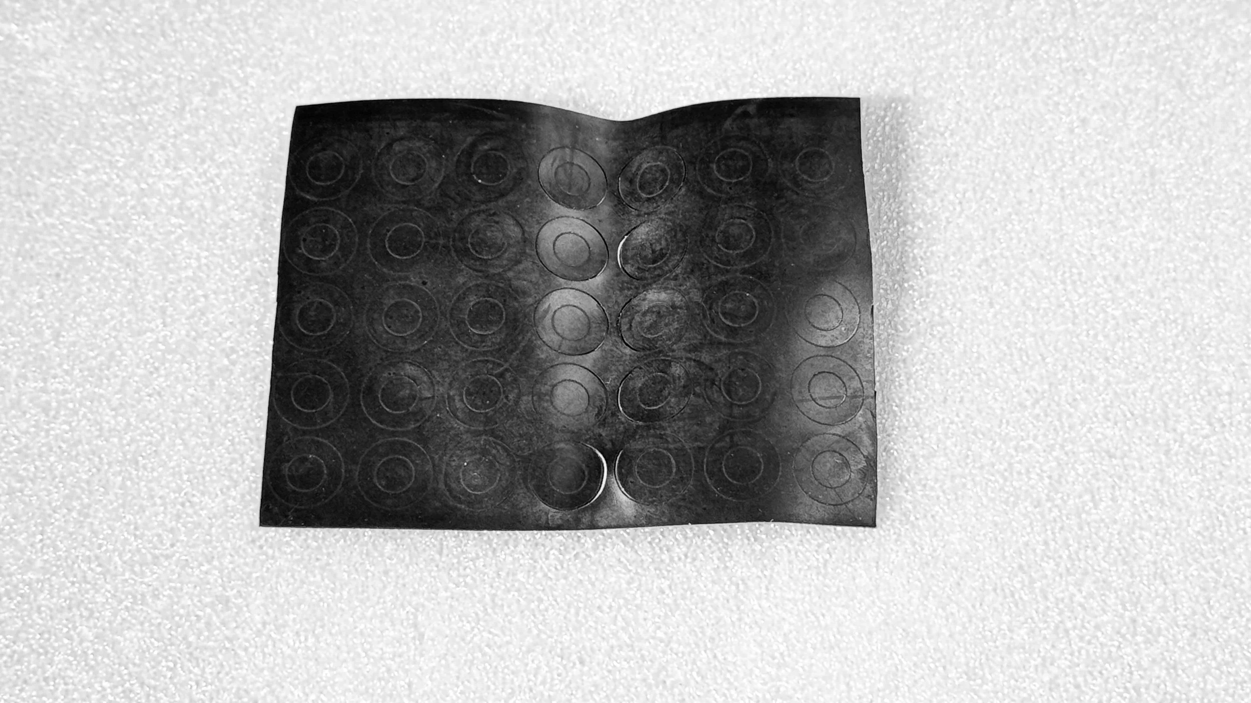
One of the more common places you may encounter light surface rust is the screw passthrough on the outer frames. This is highly avoidable by having proper step alignment, using the rubber pieces provided with your steps, not torquing down misaligned screws, which may cut through the coating.

Solution: Light surface rust in this area can be touched up with a brush. Allow the touched up paint to cure fully before using or re-installing. Enamel paints will often have an extended curing times, so please see your paint of choice for proper use and curing or baking instructions.
When spraying, use thin, light coats. This will not only help preserve the evenly textured appearance of the original powder coat, but it is also helps to prevent extended curing times.

If you live in an area that is especially known for rust and corrosion, you may also consider a topical protective coating in addition.